Rubik’s Cube Timer
This is my most recent project.
This project started out from two different thought processes: Firstly, I was two weeks out from starting university and I wanted to refresh myself by picking a project that combines CAD, hardware, and software to make something and see it through from start to finish (Spoiler: it’s not done yet…), and also, the voice in my head that always tells me ‘You can probably make this for cheaper than buying the real thing’. From personal experience, that voice is never right, but it always leads me down interesting rabbit holes. In this case I wanted to make a Rubik’s cube timer. It’s a little device that is basically a timer that senses when your hands are both on the buttons to start and stop a timer to see how fast you can solve the puzzle. Important skills, I know.
The design is simple enough. At its most basic all I need are three things: A display, a computer, and something to sense both hands. I didn’t want to use buttons because I thought I could do better so I looked into capacitive sensing. I’ve dealt with it before while trying to fix an old school computer keyboard and did some research. It turns out its really simple to make sensor pads out of even tin foil, and they can be so seamlessly integrated into 3d printed designs that I’m quite surprised on how little projects people do that use this. If anyone is unfamiliar with this, just think touch lamp.
I started off with some quick sketches in my notebook, loosely based off commercial products, but also making the design my own and much cooler. In the spirit of challenge I also decided that my timer should have a scroll wheel, integrated LEDs, a couple tactile switches and bluetooth compatibility.
I’ve done a lot of work with arduinos in the past but my requirements led me to ESP32 dev boards. I do not know how I went this long without knowing about these things because they are amazing. Plus they have built in capacitive touch pins. I sourced all the components I needed and began designing the enclosure.
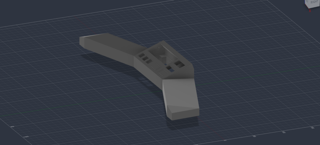
If you’ve read about some of my other projects you would see that I’m still using the same 10 year old 3d printer, so the design process was a slow one. Lost of waiting four hours to realise I made a stupid mistake and then spend 10 seconds fixing it hoping that would be the last time. I did eventually get everything to fit and the screenshots here are the final design. The scroll wheel and light cover are also done and they gave me much less trouble.
Currently, the palm pads are sensing proximity with a piece of aluminum tape stuck underneath each side, the power comes from my huge bench supply, and I haven’t decided 100% which buttons I want to use.
By this point I was done with this model-fix-print-fix cycle so I was very excited to start programming. Now, I have a decent amount of programming experience and I could have certainly churned out a working program in a few hours but that wasn’t my goal. I needed to do this right.
Object oriented programming is not a strength of mine. Yet. But I did put a lot of care into creating my classes and headers in a way that I hope is intuitive and kind to future me.
The biggest headache was deciphering the scroll wheel. I ended up desoldering the component from an old mouse I had laying around. After spending hours trying to find any information on the specific part, but eventually I just hooked everything up to my oscilloscope and decoded it that way.
I got the code written for the basic functions of the timer, the actual sensor and timing parts, averages and solve time history, and some basic settings. It’s definitely not cheaper than just buying one but, in my opinion at least, It’s much nicer looking and way more functional as it is.
Currently, I have a fully functional prototype that is running off of a breadboard an my bench power supply. Its much easier to test with all the components not in the case, but that does not stop my little brother from using it as it is. It might not be too pretty yet, but it’s so satisfying to have something I made do exactly what I made it to do.
Like a lot of things, this project is on hold while I’m off at university, but my next steps are all planned out and hopefully it won’t take too much to have a finished product. First, the usb-c boards I ordered finally came, so I can get rid of the bench supply. Then, I have to make a custom PCB. This’ll be completely new to me but I have arrived at the conclusion that it is the only way I can come close to fitting all the parts in the small enclosure. After that, I can keep adding features with my lovely modular code!